top of page


CY-GO is an ergonomically improved concept for city bikes that reduces the risk of health problems associated with inadequately fitted cycle frames.
Standard bicycle frame sizing, assigns widely ranging anthropometric groups to binary size categories that are never ideal for any one individual. Frequent use of a poorly fitting frame, such as in city commuting, can result in knee and lower back problems over time.

The bike at the final year show 2017
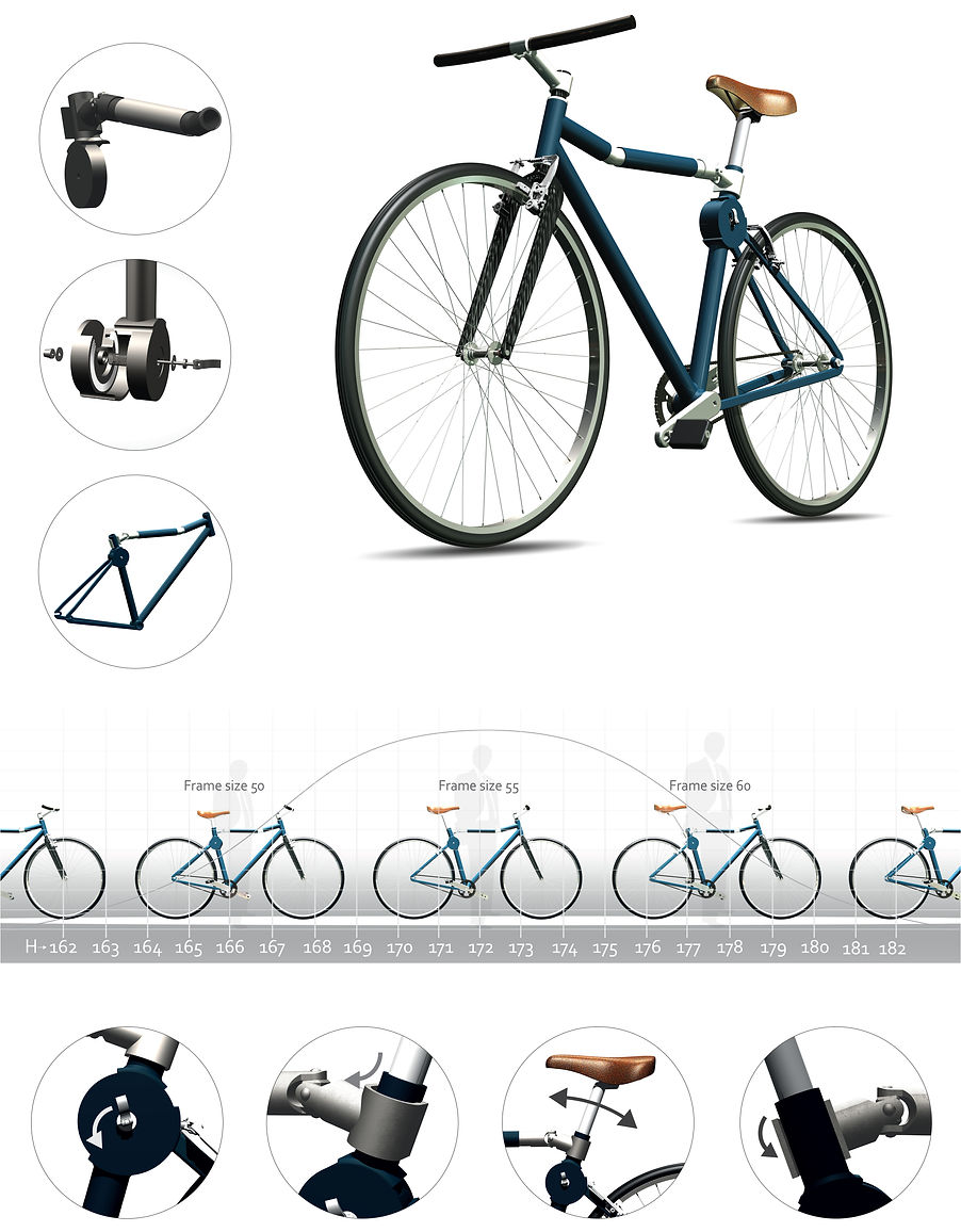
The Cy-Go novel frame system enables continuous size adjustment to provide more accurate body fit than is possible through the established system of ‘off-the-shelf’ frame sizes. Minute adjustments can be made by the user, daily, with no requirement for specialist knowledge or tools, to find the ‘perfect fit’ cycle frame size that is unique to them.
SEAT ANGLE
An adjustable bicycle frame allowing instant
and easy bike - fitting , while providing an
ergonomically improved cycling experience
CROSS-BAR
SEAT ANGLE
FRAME SIZE
ADJUSTMENTS
INSTRUCTIONS FOR USE
RELEASE
OPEN
ADJUST
SECURE
Minor adjustments on a daily basis can prevent potential lower body injuries especially among older cyclists. The frame adjustment system also enables simple conversion between road bike and lady bike configurations, a significant benefit for older riders with restricted limb mobility.
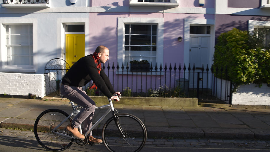
First riding test

First riding test

Final CAD rendering - Autodesk Alias
Universal joint
The adjustment
mechanism
2X bearings
Adjustable crank
length
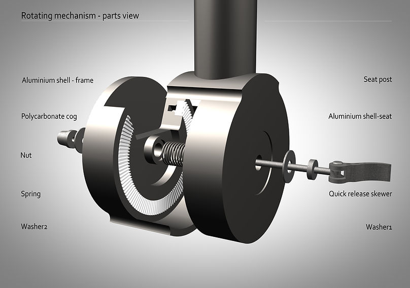
The rotating mechanism diagram
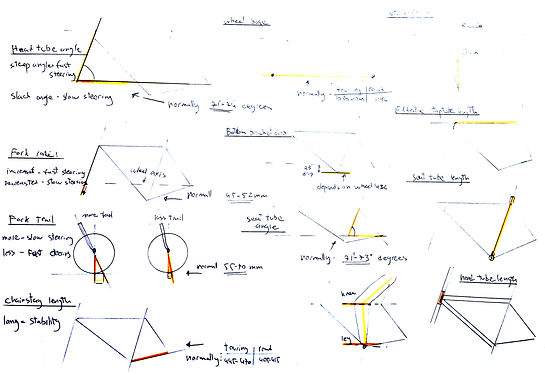
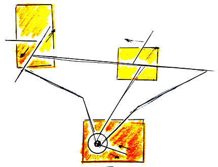
SKETCHES


RIG EXPERIMENTS
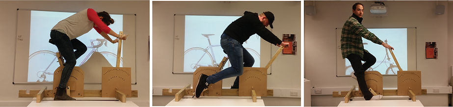
Cycling positions rig


Q-angle rig
PROTOTYPING

Frame building jig
The first stage was to cut the frame tubes and dropouts to the right sizes. In addition, each individual section was machined on the lathe/milling and sanding machine. Head tube, bottom bracket and cross bar were machined to hold the headset, bottom bracket and bearings.
Then, a special jig was built to hold the frame in position when welding it. The jig base was made of MDF, with laser cut pieces to keep the correct distances and spaces.
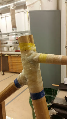
The frame was tack welded and welded inside the jig.
The headset was assembled and a carbon fibre fork was fitted. A fixed aluminium stem was used for the prototype purposes, although eventually an adjustable stem must be part of the bike.

Welding the frame
Frame assembly jig
Second jig was then built in order to align the bottom bracket, front fork and rear axle before welding the rear stays.
The two aluminium parts of the rotating mechanism were machined on the milling machine. Slots for the 3D printed cogs were milled.
Then the cogs were inserted into the aluminium shells, and the ‘bracket’- the part which links between the mechanism and the frame- was added.
Once the components of the mechanism were ready, it were assembled with the brackets, and mounted on the frame.


Machining the rotating mechanism

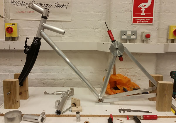
The assembled bike
And eventually, as soon as the welding part was completed, the rest of the bicycle parts were put into place. The bottom bracket, pedals and chain were assembled as well as brakes handlebar and saddle. The bearing for the cross-bar was inserted and the entire mechanism was installed.
ENGINEERING ANALYSIS - FINITE ELEMENT ANALYSIS


The British standard (BS EN 4210) - safety requirements for bicycle and in particular section 6 (BS EN 4210-6-2015) – frame and fork test method determines a few tests for frame design. The first two tests involve impact forces, whereas 3, 4, and 5 deal with fatigue tests
Meshing such a complex object was challenging. As a result of many curves and contact points, the mesh average element size was set to 0.05mm, min size to 0.1mm and max turn angle 45 degrees. Specific attention was given to the sliding elements as well as bearings and bolts. In order to get a finer mesh in the cog wheels, average element size was reduced to 0.025
Several FEA analyses, with both torsional and linear forces have indicated satisfying strength and stiffness.
Figure 74 torsional force test
In the first test, one side of the mechanism (the frame side) is completely constrained, whereas on the other part a moment force equal to 5000N is applied. Contact type was assumed as sliding/no separation and a very fine mesh was assigned to keep precision with the cogs size and angles.

Maximum Von Mises stress is 0.1763, across the smaller side of the tooth. This is a relatively low figure, still reasonable as in other simulations average stress was around 1-2MPa. Therefore, safety factor is very high (around 600!). Displacement of 0.0014mm across the all area also validate the cogs efficiency.
bottom of page